Fading Light Experiment on Arduino Kit
| ✅ Paper Type: Free Essay | ✅ Subject: Computer Science |
| ✅ Wordcount: 637 words | ✅ Published: 18 Aug 2017 |
Introduction
Arduino is an open source prototyping platform enabling users to create interactive electronic objects. [1] Here, we performed “Fading Light” one of the basic activities on this Arduino kit. This activity demonstrates the use of analog output in the code (Pulse Width Modulation) to fade the LED light. You can fade out and fade in the light of LED automatically using Arduino with a simple code that is installed in Arduino.
Materials with Description
- Arduino Board
- Arduino Uno SMD SR3 is used. The main material needed to hold the materials, and execute the code from computer.
- Prototyping Shield
- It is a prototype extension board for Arduino Board
- Resistor 220R
- 220 ohms’ resistors will be used on this experiment. It is use to reduce the current flow for the LED output.
- Bread Board
- Used for the connections of materials together.
- LED light
- (Light emitting diode) will be used for verification if the code and plotting of materials is correct.
- USB cable A-B
- USB 2.0 cable which is the common A to B M/M type peripheral cable to connect the Arduino board from computer.
- Jumper Cable M/M
- Used to connect Arduino Board from breadboard.
Procedure (self-explained)
1.Prepare the materials needed.
- 5MM -LED x1
- Jumper Cable M/M x2
- 220R Resistor x1
- USB cable
- Arduino Board
- Prototyping shield
- Breadboard
2. Place the prototyping shield on the top of Arduino Board.
3. Place LED light 1st the last row of the breadboard.
4. Place the Resistor on the Positive terminal of LED light and connect the opposite side of resistor on 10th pin using jumper wire.
5. Place the jumper wire on the Ground and the opposite side on Negative terminal of LED light.
6. Connect the Arduino Board to your desktop or laptop.
7. Now using desktop or laptop execute and install the appropriate code for Fading Light activity on your Arduino Board.
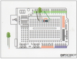
Circuit Diagram
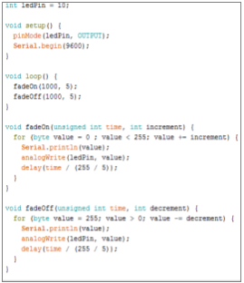
Code
Code Analysis
This is the code for Fading Light Activity. As you can see, the ledPin variable has a value of 10, 10th is the pin that the LED is attached on Arduino. On setup() function this declared pin 10 to be an output. The “Serial.begin(9600);” this code is the speed communication. Arduino will send data at 9600 bits per second which is 9600 is the default bit. Executing the loop() function which make the LED light Fade on& off with a time of 1 seconds and given value of full 5. There’s a method for fadeOn which is getting the time with 1000/ 1 sec and an increment of 5 which is called as parameters. This values are being process on for-loop which is changing the luminance of LED lights. As you can see in for-loop “(byte value = 0 ; value < 255; value += increament)" this will terminate the value is greater than 255. The value plus the value of increment which is 5 is added to the value. AnalogWrite sets the brightness of the pin 10 equals to the value. Its delay time is unsigned time which is 1000/1 sec divide by 51 which is the quotient of 255/5. Its delayed time is 19.60 sec. Opposite process for the fadeOff method its decreases the value so the luminance of LED light will decreases.
Comparison of Code vs. Hardware
Output
The given code says that LED light will fade on & off 19 times with a luminance of 5 which is the maximum luminance of it and decreases the luminance by 5. The given code output is accurate from the expected output of the hardware. It fades on & off 19 times with 5 additional luminance in every fadeOn and decreases 5 luminance in every fadeOff, the code is accurate from the output of hardware. No errors and run successfully.
Recommendation/Enhancement
I recommend that procedures, guides, or instruction are given on each group members to perform those activities successfully. Readable and reliable codes that are easy to understand. Have a review on those codes that is used.
References:
[1]Arduino:An Open Electoring Prototyping Perform
Cite This Work
To export a reference to this article please select a referencing stye below:
Related Services
View all


DMCA / Removal Request
If you are the original writer of this essay and no longer wish to have your work published on UKEssays.com then please click the following link to email our support team:
Request essay removal