The Use of CES to Compare Engineering Materials
| ✅ Paper Type: Free Essay | ✅ Subject: Engineering |
| ✅ Wordcount: 2135 words | ✅ Published: 10 May 2021 |
1 – Introduction
In engineering, the selection of materials is one of the most critical stages in the design phase. Engineers, designers, and contractors must make, not only the best choices possible, but also the correct choice when presented with a task. This is to ensure the material selected performs the job it is tasked with doing. The only way to make these choices is by understanding the constraints of the design and the requirements at hand. Without these fundamental properties, a situation may arise where something goes wrong due to a small difference in a materials property which could affect service life, structural integrity and more importantly the safety of the user(s). Due to all these factors, ensuring that the right material is selected is of utmost importance in any field.
This report will outline the steps that had to be taken to find the top 6 ranked materials by using Cambridge Engineering Selector (CES) to use in the manufacture of a flywheel for efficient energy storage which stores as much energy per unit weight by analysis of material indices.
2 – Methodology
2.1 Translating the problem
In the modern era, companies of design and manufacture can depend on vast databases and software programmes that assist them in their selection of materials. CES is an important selection programme that allows engineers to first compare but then also choose the material relevant to their task. The benefit of using this database is that by entering certain constraint parameters, the software can screen thousands of materials in just several seconds.
The constraints for this task were used to form certain relationships or dimensionless variables in the form of material indices. A material index is a combination of material properties that characterise the performance of a material with a specific purpose [1].
For this material selection, the goal was to use CES to screen and then identify the top six materials to be used in a flywheel for efficient energy storage systems. The material must be able to store as much energy per unit mass as possible without failure. The breakdown for the task can be seen in Table 1 below:
|
Function |
Flywheel |
|
Objective |
Store as much energy per unit mass
without failure |
|
Constraints |
|
Table 1 – Design requirements for flywheel task.
2.2 Material Index Analysis
The material index for the flywheel was calculated by manipulating the equations in the steps that are shown below. [2]
R is the fixed radius of the disk; t is the thickness and is the angular velocity during rotation.
Where is the moment of inertia of the flywheel disk and is the density of the material used. After some simplification, this equation leads to:
The mass of the disk is given as:
Therefore, to find the maximum energy per unit mass, equation 2 is divided by 3 to give us:
The maximum centrifugal stress is given as:
As mentioned above in Table 1, the centrifugal stress must not be greater than the failure stress and that the flywheel must hold as much energy per unit mass. From these given parameters, manipulation of ratios can be carried out to find the final which will in turn give the material index required.
Following these manipulations, the material index required is given as:
This shows that the materials with the highest ratio of ultimate tensile strength over density will be best suited to be picked for the manufacture of the flywheel in this project.
Finally, a second material index must be used. When looking at the table with constraints, cost per kilogram and toughness must form a simple ratio. This gives:
Where G is the toughness of the materials and C is the cost.
2.3 Material Screening using CES
Following the establishment of the two material indices, the next phase is to commence the material screening on the CES database. A graph of ultimate tensile strength versus density (M1) was plotted on a logarithmic scale and the stored materials were shown. Figure 1 below shows the results obtained.

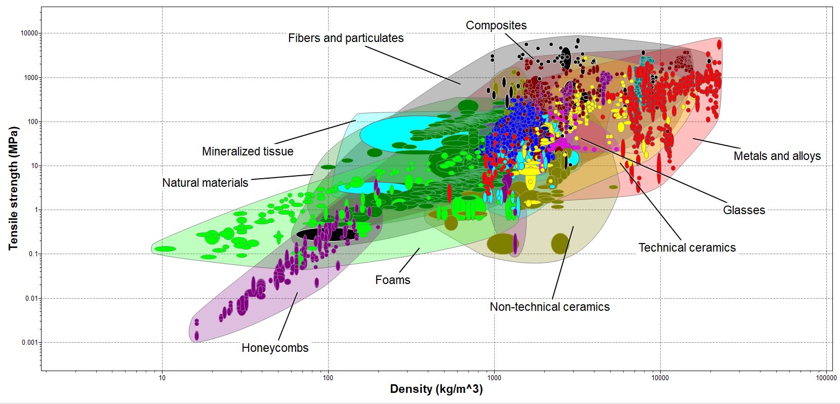
Figure 1 – Stage 1 Plot (Tensile Strength vs Density)
Once all the materials from the database were supplied on the chart, filtering for materials could continue. A line of gradient 1 was plotted on the graph which allows the user to be able to change the position gradually. This enables materials below to be eliminated until the point occurs that only materials remain. Figure 2 below shows the updated chart.
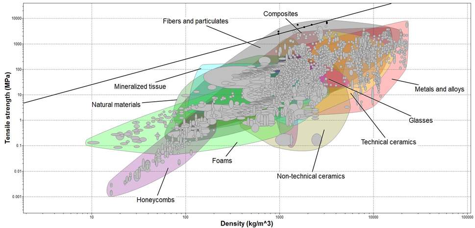
Figure 2 – Stage 1 plot with line of gradient 1 showing passed materials highlighted in Black.
Once the first stage was completed, M2 was then plot on a second graph. Once again it was plot on a logarithmic scale. Following the plot of the chart, a box was added in the region where the appropriate toughness and cost regions would occur. Straight lines (horizontal/vertical) were not used due to the fact they would represent limits. In the case of this project, toughness and cost are secondary constraints and were left arbitrary.
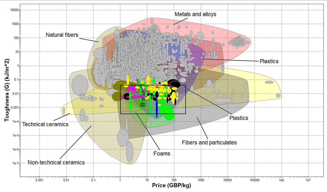
Figure 3 – Stage 2 plot with limit box (Toughness vs Cost/kg)
Finally, by using the intersection button on CS, the screening was completed. By using this function, it allows the user to identify which materials passed both stages from the given parameters. Figure 4 shows the combination of both stages and the final materials are named in Table 2
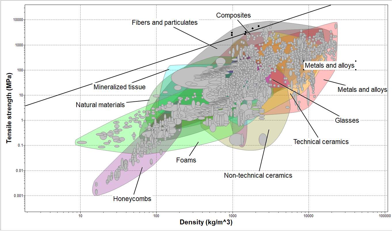
Figure 4 – Completed screening (materials that passed both stages)
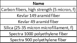
Table 2 – Final materials in alphabetical order
2.4 Ranking of Materials
Now that the top six materials are found, further consideration can take place to form a final judgement on which material is to be ranked top. To assist in the final decision, current knowledge on material science will be used as well as considering published studies regarding similar work. Using the CES database, the materials characteristics will also be recorded and compared with one another. For this case, tensile strength, density, and toughness were compared and these influenced the final ranking. Toughness had to be considered due to the original constraint in Table 1 of the flywheel requiring a crack tolerance.
For each material property, a range of values were given on the CES software. To avoid any major discrepancies, the minimum value was taken into consideration. The reason for this is that not all the sample materials may be able to reach their maximum value therefore, the minimum values will be less likely to cause errors. Shown below in Table 3 is the final ranking of materials.
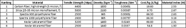
Table 3 – Final material ranking
The overall first place material was the “Carbon Fiber, high strength (5-micron, f)” also known as Carbon Fiber Reinforced Polymer (CFRP). The reasoning for this decision is that although the silica has a higher Material Index, meaning that in theory it will store more energy per unit mass, the CFRP has a higher toughness value. This is key because the CFRP disk will be able to endure more fatigue due to cracking and still be able to perform.
Also, CFRP’s have been tried and tested in this role. It has been shown that they can store approximately 200kJ/kg whereas a traditional material such us lead can only store around 1kJ/kg making it ideal for modern use. Finally, the material has a low density which allows it to be lightweight, yet it still have a high tensile strength meaning the structural integrity of the flywheel will not be an issue. When looking at toughness, although it is lower than the Silica, the ratio of toughness compared to the other parameters is very similar to that of the second ranked material.
Although the Carbon Fiber is almost double the cost of the silica, the safety of the user should be the main priority. The reason for this high cost is the time-consuming manufacturing of the material in that lattice sheets must be woven from a single carbon strands and a resin is used to keep it in its final shape due to it being synthetically produced.
Finally, materials ranked 3-6 are not suitable for this type of application. This is because they are fabric materials used in the applications of electrical wiring insulation. Due to this, they would not be suitable in producing a solid disk that rotates and at the high rotation speeds they could rip themselves apart causing damage to the product they are used in.
3 – Critical Discussion
3.1 Ashby Charts
The charts from CES shown in Figure 2 and 3 depict how different material families perform under the given characteristics. The different material envelopes highlighted in the figures show a range of materials that include low density, light foams in the bottom left to high density, heavy Tungsten materials in the top right. By using the software, it allows the scanning of materials on both extremes of the material spectrum to be analysed and included. By adjusting the straight linear plot on the graph, the optimum material could be found with relative ease and the remaining materials could be eliminated in this screening process due to the gradient of the given line. This shows that the main reason for materials being eliminated is due to the order of the material index that was calculated. For example, if the tensile strength were greater, this would cause a steeper gradient to occur and would produces a greater number of materials to be included.
3.2 Other Considered Factors
The main characteristics used for this task was the density of the material and the tensile strength. Although these did not have numerical values applied to them, sensible estimates had to be considered. As an example, if the material used was to dense (e.g. tungsten) then the weight of the flywheel would be to great and the energy stored would not be adequate to rotate it.
Other factors that were considered for this project, for ranking and as a material index, were the cost of materials and the toughness. The cost of the material had to be economical for the application otherwise the device could have been manufactured at a loss. The cost must be justified when choosing a more expensive material such as the Carbon Fiber. As mentioned earlier, the CFRP has been used safely in this application meaning the safety factor and prior use justifies the cost. As for the toughness, it was the same situation as the cost in that no fixed value was set although a sensible value had to be decided on.
Finally, the radius of the flywheel was left arbitrary. If a selected value were decided upon, it would again mean that certain materials would be omitted or made available. This is because geometric parameters of any structure play a major part in performance and changing the size or shape could cause the material to act differently when the final product is produced.
3.3 Advantages & Disadvantages of Using CES
A great advantage of using CES is the ease of use. An inexperienced individual can easily navigate around the software and prior knowledge is not key for use. Training on it is easy and due to the vast number of people using it, resources are readily available either on the software itself or online to the general public due to it being used as a current analysis tool in industry. Another key advantage is the large number of properties that can be analysed. Numerous combinations can be plotted on the charts to find relevant relationships for different material indices to achieve a vast number of depictions to choose materials for a given specification.
The main disadvantage of the software however is the generalisation of the materials. Although thousands of materials are stored on the database, the variations of each material are basic. Only modern materials such as the Carbon Fiber composite have variations stored whereas more well-known and older materials contain a limited amount. Another disadvantage due to these variations are the range of values of properties that are given for materials. For some materials, the range of values are large, this could cause issues. A material may not reach a stated value on the software due to being a variation and this could cause issues for manufactures.
3.4 Individual Feedback
Overall, I believe that CES is a key part of any design process. After seeing the ease of use for the software, it has allowed an engineering student to select and compare materials for a given task with reliability and maximum efficiency. I feel that this software will be used more regularly in the future as it will allow me to solve any future material selection processes that may occur.
References
[1] City, University of London “Lecture 2 – Selection of Materials”
[2] Michael F. Ashby “Materials Selection in Mechanical Design” 5th Edition (2017)
Cite This Work
To export a reference to this article please select a referencing stye below:
Related Services
View all


DMCA / Removal Request
If you are the original writer of this essay and no longer wish to have your work published on UKEssays.com then please click the following link to email our support team:
Request essay removal