Digital Clock Using AT89C51
| ✅ Paper Type: Free Essay | ✅ Subject: Engineering |
| ✅ Wordcount: 1880 words | ✅ Published: 18 May 2020 |

Keywords: Digital Clock; LCD Display; 8051Microcontroller
Abstract
A digital clock was designed in the this project where the microcontroller is used for the timing controller as well as the programming in the microcontroller is performed. The design is cost effective, simple and easy for maintenance.
A clock is an instrument for measuring time. In principle it requires no more than some physical process which will proceed at a known rate, and a way to gauge how long that process has been continuing.
Digital clocks display a numeric representation of time. Two numeric display formats are commonly used on digital clocks. They are: 24-hour notation with hours ranging 00 to 23 and 12 hour notation with AM/PM indicator. Most digital clocks use an LCD or LED display.Generally for the designing a digital clock, a microcontroller is used as the controller of the circuit and a Real Time Clock IC is used as counter.
Our approach is to simulate the clock circuitry in Proteus 8.1 software with all the necessary interfacing connection and program. After simulating in the Proteus, we move to hardware implementation of the Digital clock.
Introduction
Electronic clocks are widely used instead of Mechanical Clocks. The reason is Digital clocks are portable reliable, accurate and maintenance free. Digital clocks are more common and independent of external source. To implement a Digital Clock, we require software. Microcontroller control system will use this software for its functioning. This Paper will describe how we have constructed the microcontroller based Digital Clock is constructed with ATMEL 89C51.
AT89C51
The Chip we use is AT89C51. AT89C51 is an 8-bit microcontroller which belongs to Atmel’s 8051 circle of relatives. We use 4KB of Flash present in AT89C51 to area our program hex file. This is erasable study handiest memory (PEROM). It additionally has 128bytes of RAM. AT89C51 is a 40 pin tool and it has four ports special as P1, P2, P3 and P0. All these ports are eight-bit ports and can be used as both enter and output ports. Except P0 which wishes outside pull-ups, rest of the ports have inner pull-ups. When 1s are written to these port pins, they are pulled high through the internal pull-united statesand may be used as inputs. These ports also are bit addressable and so their bits also can be accessed personally.
Port P0 and P2 are also used to provide low byte and high byte addresses, respectively, while linked to an outside reminiscence. Port 3 has multiplexed pins for unique capabilities like serial verbal exchange, hardware interrupts, timer inputs and read/write operation from outside memory. AT89C51 has an inbuilt UART for serial communication. It can be programmed to perform at different baud quotes. Including timers & hardware interrupts, it has a complete of six interrupts.
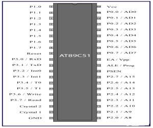
Fig1. Pin Discription of AT89CS51
Block diagram:-
POWER SUPPLY
MICROCONTROLLER
8051
TIME DISPLAY


REQUIRENT –
8051 microcontroller
Seven segment display
Crystal 11.0592 Mhz
Capacitor
8051 Microcontroller
Resistor
LCD display
A Liquid-Crystal Display (LCD) is a flat panel display, digital visible display, or video show that uses the mild modulating houses of liquid crystals. Liquid crystals do not emit mild without delay. LCDs are to be had to display arbitrary images (as in a wellknown-reason laptop display) or constant photos with low facts content material which may be displayed or hidden, which include preset phrases, digits, and seven-segment shows as in a digital clock. They use the same basic generation, except that arbitrary snap shots are made up of a large variety of small pixels, even as other shows have large elements. LCDs are utilized in a extensive range of packages such as laptop monitors, televisions.

A Liquid crystal show is a special thin flat panel that may permit mild undergo it, or can block the light. (Unlike an LED it does no longer produce its very own light). The panel is made up of several blocks, and each block can be in any form.
Liquid crystal shows are often used in battery-powered gadgets, together with virtual watches, due to the fact they use very little power. They also are used for flat display TV’s. Many LCDs paintings properly through themselves whilst there may be other light round (like in a lit room, or outdoor in daylight hours). For smartphones, laptop monitor, TV’s and some other purposes, a lower back-mild is constructed into the product.Some passive matrix LCD’s have dual scanning, meaning that they experiment the grid two times with contemporary inside the identical time that it took for one scan in the authentic technology. However, energetic matrix continues to be a superior technology.

Fig.2. LCD Display
They are common in client devices which includes DVD gamers, gaming gadgets, clocks, watches, calculators, and phones, and have replaced cathode ray tube (CRT) shows in nearly all applications. They are available in a much broader variety of display sizes than CRT and plasma presentations, and when you consider that they do no longer use phosphors, they do no longer suffer photograph burn-in. LCDs are, however, susceptible to picture endurance. The LCD screen is extra power efficient and may be disposed of more adequately than a CRT. Its low electric power consumption enables it to be used in battery-powered digital system. It is an electronically modulated optical device made from any range of segments controlling a layer of liquid crystals and arrayed in front of a mild source (backlight)
or reflector to produce snap shots in coloration or monochrome. Liquid crystals were first determined in 1888. By 2008, annual sales of televisions with LCD monitors passed income of CRT gadgets global, and the CRT became out of date for most purposes.
Interfacing AT89C51 with LCD display
The Circuit diagram given above suggests how to interface a 16×2 LCD module with AT89S1 microcontroller. Capacitor C3, resistor R3 and push button transfer S1 paperwork the reset circuitry. Ceramic capacitors C1,C2 and crystal X1 is associated with the clock circuitry which produces the gadget clock frequency. P1.Zero to P1.7 pins of the microcontroller is hooked up to the DB0 to DB7 pins of the module respectively and thru this path the data is going to the LCD module.
P3.3, P3.Four and P3.5 are linked to the E, R/W, RS pins of the microcontroller and via this direction the manipulate indicators are transferred to the LCD module. Resistor R1 limits the current through the returned light LED and so do the returned moderate intensity. POT R2 is used for adjusting the assessment of the show.

Fig3. Interfacing of AT89C51 with LCD Display
Simulation of digital clock in proteus
Connections are made as shown in the circuit diagram below. Then we developed the program and run in Keil to obtain the hex file after debugging . We open this hex file in the AT89C51. We can check whether our program is working. After conforming this we then go for the connecting the discrete components.

Fig4. Circuit Diagram showing all connections
The following steps of connections are followed.
STEP1: PINS 28-21 of the microcontroller are connected to the PINS 7-14 of the LCD display. STEP2: PINS 16,11,10 of the microcontroller are connected to the PINS 4,5,6 of the LCD display. STEP3: PINS 18,19 of the microcontroller are connected to the oscillator.
STEP4: PINS 1,2,3 of the microcontroller are connected to the switches S1,S1,S3. STEP5: PINS 1,2,3 of the microcontroller are also connected with resistors R1,R2,R3.
STEP6: PIN 20 of the microcontroller is connected to GND and PIN 16 of LCD display is connected to vcc.
STEP7: PIN 15 of the LCD display is connected to +5V.
PROTEUS CIRCUIT OF DIGITAL CLOCK WITH USING 8051 MICROCONTROLLER

Hardware implementation of digital clock
The power is supplied to components like regulator, resistors and Microcontroller control circuitry using a 12V/3.2A battery and microcontroller requires 5V .with the help of regulators we regulate the power between three components. This Clock works in 12 hour mode and is configured by programming the microcontroller AT89C51. The program uses a delay function for producing a delay of 1 second.
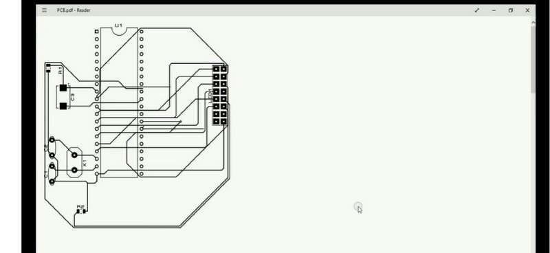
P.C.B LAYOUT
On PCBsoftware, the whole circuit was intended. PCB circuit layout and preparations in any printed circuit board are the first and most significant. First component layouts were designed according to the component dimensions available in PCB software. The following points are to be observed during PCB design:1
There should be enough room between two parts to prevent partial contacts2
High voltage dissipated parts should be installed at a sufficient distance from semiconductor and electrolytic capacitors. Printed circuit board (P.B.C) is used to prevent most of the disadvantages of breadboard convection. These also prevent thin cables from being used to connect the parts.

CHALLENGING
Digital clock based on microcontroller was a large challenge for us. We have experienced so many issues in this project from circuit design to simulation.
Coding and design-The most significant and first phase of any project is coding and design. Our project was very complex because the PC used Rs232 cable to control it. So it was a lot of hard design. After so much surfing on the internet, we disused our guide. We did the coding (microcontroller tutorial) effectively and completed the project layout.
Simulation – We experienced problems in discovering software that could interface with Proteus software during simulation. There was no microcontroller available in the Matlab SO We searched the internet and after watching videos on your tube, we found keil software that has 8051 microcontroller and is able to interact with Proteus software.
Arranging Equipment-Now it was time to work on the hardware after simulation completion so we searched the entire element of electronics online or in local shops. But in the local market we didn’t discover equipment. So we ordered internet equipment.
Establishing interaction between microcontroller and PC — Communicating microcontroller with PC using RS232 and MAX232 was a major challenge for us as we never worked on this sort of communication job. Without hardware, this communication was not feasible. I intended a circuit using 3 led to give input to the microcontroller and get output from the microcontroller, which can be regulated by the keyboard after pressing + x + y + z buttons using virtual terminal.
CONCLUSION-
Overall, this project has been accomplished effectively and fulfills the overall project goal and goals. The new digital clock system is a microcontroller-based system that allows easy reprogramming of the required outcomes compared to the hardware-based scheme that uses fixed timing systems. By studying microcontrollers, it is evident that it is much easier to design a digital clock than to use counters for decades. To make this easier, however, the microcontroller needs to be programmed to produce and regulate the time. As well as programming and working with microcontrollers, troubleshooting methods have been learned.
References
- https://www.youtube.com/watch?v=7z2yLCq9Qk4. (n.d.).
- keil. (n.d.). Retrieved from http://www2.keil.com/mdk5/uvision/
- microcontroller tutorial. (n.d.). Retrieved from https://techetrx.com/8051-microcontroller-tutorials/programming-8051-microcontroller-using-rs232/
- proteus software. (n.d.). Retrieved from https://www.labcenter.com/downloads/
- virtual terminal control in proteus. (n.d.). Retrieved from http://www.circuitstoday.com/virtual-com-ports-proteus
Cite This Work
To export a reference to this article please select a referencing stye below:
Related Services
View all


DMCA / Removal Request
If you are the original writer of this essay and no longer wish to have your work published on UKEssays.com then please click the following link to email our support team:
Request essay removal