Non-visual Motion Tracking
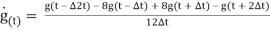
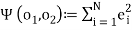
| ✅ Paper Type: Free Essay | ✅ Subject: Engineering |
| ✅ Wordcount: 2587 words | ✅ Published: 30 Aug 2017 |
Additionally, (Taylor et al. 2010) demonstrated that the OSSCA method, which employs a combined use of OCST, SCoRE, and SARA techniques to process marker data and allows the estimation of joint parameters from kinematic data alone, without the necessity to use generic anatomical relationship assumptions, returns more reliable, repeatable and reproducible results than a standard generic regression approach.
Although the accuracy of the data acquired by means of optical motion capture systems is very high in the controlled environment of the lab, the ambulatory use of this type of equipment is cumbersome and presents significant limitations which can not only compromise the precision of the acquired data, e.g. dependency on line-of-sight, limited range and latency of data (Schepers et al. 2010), but also the practicability of the acquisition itself, e.g. necessity of power source, set-up time, outdoor calibration of the system.
- Non-visual motion tracking
Non-visual motion tracking is a sensor based technique, which can be carried out, amongst others, with acoustic, magnetic, or inertial sensors, or with a combination of these methods.
Ultrasound based acoustic systems, e.g. ‘the Bat system’ (Ward et al. 1997), ‘Vallidis’ (Hazas and Ward 2002), ‘the Cricket location system’ (Priyantha et al. 2000) and ‘WearTrack’ (Foxlin and Harrington 2000), are capable of tracking the locations of pulse emitting beckons by using the time-of-flight information of audio signals.
This type of motion tracking system is wireless, however, as with visual motion tracking, occlusion of the signal emitter poses a significant limitation.
In contrast, magnetic systems, e.g. MotionStar® (Ascension Technology), are capable of estimating their position and orientation within the global coordinate system, by using information from the local magnetic environment, and are, therefore, not constricted by line-of-sight. However, these systems are very sensitive to ferromagnetic interferences.
Inertial motion capture systems, e.g. Moven (Xsens Technologies) and Alert (Verhaert), employ the use of accelerometer and gyroscopes to measure inclination angles. These systems are highly accurate, however, sensitive to vibration and subject to integration drift over time.
In fact, throughout the past decade, the use of inertial sensors has gained increased popularity within researchers (Foxlin 1996; Roetenberg et al. 2007a; Roetenberg et al. 2005; Roetenberg et al. 2009; Roetenberg et al. 2003; Roetenberg et al. 2007b; Roetenberg and Veltink 2005), as well as general population.
Many people schedule their daily activity based on the data presented by certain applications on their smartphones (e.g. Health app, Argus, MyFitnessPal), their smartwatches (e.g. Sony, LG, AppleWatch, Fitbit Surge) or pedometers and wristbands (e.g. Fitbit Flex, Garmin vivofit, Polar Loop, Jawbone).
However, in the field of research, there is a need for more complex systems, which can provide more comprehensive information, of a larger variety.
For this purpose, hybrid systems, combine the use of different techniques to compensate for the shortcomings of individual systems. Such hybrid systems are represented by acoustic-inertial systems (Vlasic et al. 2007; Ward et al. 2005), e.g. Constellationâ„¢ (Foxlin et al. 1998), optical-inertial systems, e.g. Hy-Birdâ„¢ (Ascension Technology) and inertial-magnetic systems, e.g. MERG sensors (Bachmann 2000), MTw development kit (Xsens Technologies), MVN Biomech and MVN Awinda (Xsens Technologies).
Combined inertial and magnetic sensing is currently one of the more popular choices in this area of study and will be discussed at length in the following paragraphs.
The light weight, wireless and cheap, inertial sensors equipped with accelerometers, gyroscopes and magnetometers enable, when positioned on the human body, the computation of angular orientation of the anatomical segments to which they are attached to (Bellusci et al. 2013; Roetenberg et al. 2003).

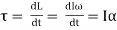
The on-board gyroscopes measure angular velocity, based on the principle of angular momentum, according to the following fundamental equation:
 (1)
(1)
Where: Ï„ – torque on the gyroscope; L – angular momentum; I – moment of inertia;
ω – angular velocity; α – angular acceleration.
The most commonly used gyroscopes for human motion studies are piezo-electric, capable of detecting vibration of mass.
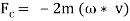
When an object vibrates while rotating, it is subject to the Coriolis Effect. This causes a second vibration to occur orthogonally to the initial vibration direction. The rate of turn can be calculated from this latter vibration. According to the following equations:
 (2)
(2)
Where: m – mass; á´ – momentary speed of the mass with reference to the moving object to which it is attached.
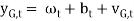
The resulting gyroscope signals are then defined as being the sum of angular velocity ωt, offset due to temperature of gyroscope bt, and white noise ᴠG,t (Eq. 3).
 (3)
(3)
The gyroscope output is very accurate, however, it is subject to errors and drift caused by integration of the signal over time, and the gyroscope temperature which can produce small offset errors, leading to large integration errors when calculating orientation.
The use of compensatory estimation algorithms, such as Kalman filters can reduce the inherent errors in the gyroscope output signal (Roetenberg et al. 2003). Kalman filters are mathematical algorithms used to efficiently minimize the mean of the squared error of a system output (Welch and Bishop 1995). Kalman filters are particularly useful for combining parameters of different measurement systems so that the advantages of one compensates for the weakness of the other, e.g. accelerometers are often used in conjunction with gyroscopes, in order to compensate for inclination drifts in the gyroscope signal.
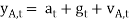
The accelerometers measure the gravitational acceleration g and the vector sum of acceleration a. The output accelerometer signals are defined as the sum of acceleration at, gravity gt and white noise á´ A,t.
 (4)
(4)
The inclination information provided by gt can be used to correct the orientation drifts of the gyroscope (Roetenberg et al. 2003). A further common example of Kalman filtering, is using magnetometer readings to correct for the gyroscope’s vertical axis drifts (Roetenberg et al. 2003).
Magnetometers have the ability to detect local magnetic north and adjust heading direction. The principles by which the magnetometers work are described by following equation:
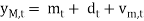 (5)
(5)
Where: ym,t – magnetic signals; mt – earth magnetic field vector;
dt – disturbance vector;
vm,t -white noise.
In real life measuring conditions the distribution of the magnetic field is often more complex and other parameters, such as changes in magnetic flux and the magnetic inclination angle, which can affect the magnitude of the magnetic disturbance, should be taken in consideration.
The major limitations of using inertial and magnetic sensing for motion tracking are represented by the following factors:
- Ferromagnetic interferences can distort the local magnetic field and affect the measurements for the orientation about the vertical axis (Roetenberg et al. 2003).
- The velocity and type of movement performed and the geometry of the body segment to which the sensor is applied can affect the accuracy of the measurements (Roetenberg et al. 2005);
- Distances between body segments cannot be assessed by means of numerical integration (Roetenberg and Veltink 2005);
Previous studies in which this type of equipment was used report a high accuracy of the output data (Cutti et al. 2010; Ferrari et al. 2010a; Seel et al. 2014), however, the limitations in using this motion capture system are far from being overcome. The most important and challenging aspect of the study is to use the acquired information in a biomechanically meaningful manner, e.g. the parameters declared as joint angles, need to be as anatomically accurate as possible, for this purpose assuming the joint angles can be calculated as the angles of movement between two anatomical segments is not enough, a more complex mathematical model needs to be developed in order to address the biomechanical characteristics of the studied joint.
There are a variety of protocols and algorithms available for post processing of sensor data stemming from human motion studies. A common approach for solving a human kinematics problem is to compare the human body to a robot manipulator. Similarly to a robot manipulator, which forms a kinematic chain from links interconnected by joints, the human body can be considered a kinematic chain formed of anatomical segments connected by articulations. In theory, this is a very efficient manner to solve a biomechanical problem.
Cutti et al., for example, use the Danavit-Hartenberg convention of robotics in their “Outwalk” protocol, which states that a kinematic chain with n joints will have n+1 links (Fig 2.4). To solve the kinematics, a coordinate system is rigidly attached to each link. In this case, when joint  is actuated, the adjacent
  and its attached coordinate frame
  perform a motion. Whichever motion is performed by the kinematic chain, the coordinates of each point on are constant when expressed in the
  coordinate frame (Zatsiorsky 1998).
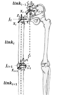
The Danavit-Hartenberg convention has two conditions which need to be satisfied in order for the kinematic solution to be effective. The variables of a joint (e.g. rotation angles) are defined by the two coordinate systems of the links adjacent to the joint. So, for example, the coordinates of the frame are expressed in the  frame. Firstly, the orthonormality of the frames needs to be established, meaning
  needs to be perpendicular to
  . Secondly, the projection of in the frame ought to intersect .
Comparing the human body to a robotics model is a good starting point. However, using the, frequently associated, strap-down integration method when measuring human kinematics with sensing units poses a very important limitation (Seel et al. 2014). The strap-down-integration method is based on using sensing units securely fixed to the even surfaces of robotic elements. However, there is a significant difference between a robotic setup and an anatomical system.
Firstly, aligning the sensor to an anatomical location, such that one axes of the sensor coordinate system coincides exactly with an axis of the anatomical joint, is nearly impossible (Seel et al. 2014). This issue has been addressed in different manners by researchers so far.
In the “Outwalk” protocol, Cutti and Ferrari et al. define as many coordinate frames for each link as the joints they form. Each anatomical segment has, therefore, a distal and a proximal coordinate frame. The joint variables are defined by the distal coordinate frame of one segment and the proximal coordinate frame of its adjacent segment.
Another issue that needs to be addressed, when discussing a human biomechanical model, is an almost certain misalignment of the thigh axis with the segments’ coordinate system. Some studies completely ignore the misalignment between the anatomical and the sensor axes (Seel et al. 2014). In the “Outwalk” protocol this problem is solved by expressing the flexion-extension axis of the knee in the coordinate system of the distal femur and defining the other revolution axes of the coordinate frame as being orthogonal with respect to the new axis.
This is another promising approach, however, in order for this method to be effective, the knee flexion-extension axis needs to be accurately identified.
In the case of hinge joints, such as the simplified model of a knee joint, it is possible to calculate data from inertial sensors attached to both ends of the joint. However, this resulting data still needs to be translated into joint related coordinate systems and although, it is impossible to determine the initial position of the sensors on the anatomical segment, there is a possibility to determine the direction of the joint axes, by using different approaches to identify a functional movement axis from a set of dynamic motion data (Cutti et al. 2010; Ferrari et al. 2010a; Seel et al. 2014).
In their protocol Cutti and Ferrari et al. use Woltring’s mathematical solution for determining the finite helical axis (reviewed in (Zatsiorsky 1998)) to identify the knee flexion-extension axis. Woltring’s solution appears to be fitting at least for most motion capture systems (Seel et al. 2014). However, the sensing units used in our study cannot measure translation. This would pose a big problem and could potentially result in substantial errors.
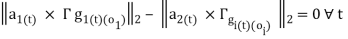
In order for the outcome of the study to be successful, it needs to satisfy a set of conditions: (1) it is very important that the resulting post-processed sensor data is biomechanically meaningful to the musculoskeletal system; (2) data acquisition needs to be user friendly, rapid and easy to complete; (2) sensor mounting is not allowed to restrict the participant’s movement in any manner; (3) the resulting data needs to relate to true anatomical joint angles; and (4) the resulting information needs to be comparable to the reference system (Vicon).
Seel et al. offer a solution based on rotational angle estimates alone, which is not only more simple from a data acquisition and processing point of view, but also functions on principles similar to SARA and SCoRE.
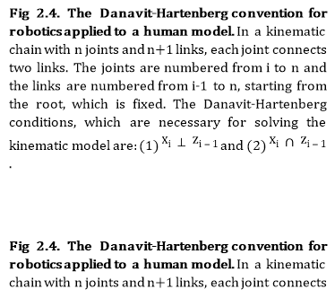
In the protocol proposed by Seel et al. the knee is assumed to be a simple hinge, with one sensor attached to each segment forming the joint. In order to compensate for the lack of information concerning the initial position of the sensors on the anatomical segments, the unit length direction vectors and the orientations of the two segments attached to the hinge joint (Fig 2.6) are estimated as described below.
The Seel et al. solution only employs the use of what is considered to be “raw” accelerometer and gyroscope output data from the two sensors, the thigh sensor and the shank sensor. In reality, any output data produced by the Xsens sensors, used in Seel et al.’s study and the current study, is pre-processed in real-time by the on-board Kalman filter.
For the purpose of the summary of the following protocol, all data indexed with 1 refers to thigh sensor data and data derived there from, and all data indexed with 2 refers to shank data and data derived there from.
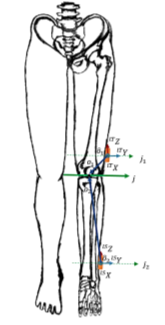
Firstly, the unit length direction vectors of the flexion-extension axis of the knee  , are identified in the local coordinates of the sensors, by using an optimisation algorithm to compute the values of
  . Where the spherical coordinates for
  are:
are:
 (6)
(6)
 (7)
(7)
With the following sum of squared errors:
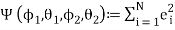 ;
; 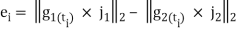 (8)
(8)
A search function is then used to find which satisfy the following condition:
 (9)
(9)
Where: 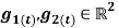 angular rates recorded by the thigh and shank sensor, respectively, with the sample period:
  – constant;
  – Euclidean norm.
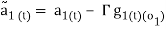
The acceleration measured by each sensor  is the sum of the acceleration due to movement around the joint centre and the acceleration due to the rotation of the sensor around the joint centre. In order to estimate the knee joint position
  expressed in the local coordinate systems of the sensors, the amounts by which
  are shifted in order to obtain the acceleration of the joint centre, are estimated first.
Two arbitrary points along the  axes
axes  are estimated using a Gauss-Newton optimization algorithm. These points are shifted as close as possible to the sensor origin by applying:
 (10)
(10)
 (11)
(11)
The radial and tangential acceleration due to the rotation of the sensor around the joint centre is computed:

 ; i=1,2 (12)
Where:  are time derivatives for angular rate and
 (13)
(13)
The following sum of squared errors is calculated:
 ;
;  (14)
(14)
A search function is used to find  which satisfy the following constrain:
 (15)
(15)
The knee flexion/extension angle based on the gyroscope information is calculated with the following equation:
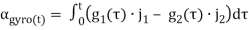 (16)
(16)
The measured accelerations are shifted onto the joint axes by applying the following:
 (17)
(17)
 (18)
(18)
Where,  represent the same quantity in the two different local coordinate systems, which rotate with respect to each other around the flexion axis.
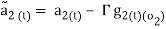
The flexion/extension angle calculated according to acceleration data  can be defined as the angle between the projections of
  .
.
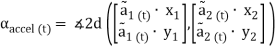 (19)
(19)
Where,  and
and 
 are pairs of joint plane axes, defined by:


 ;
;

The knee flexion/extension angle defined by fusing the accelerometer and gyro data is defined by:
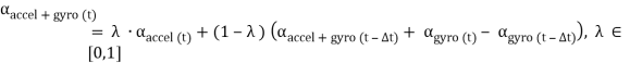 (20)
(20)
Where:  – knee flexion extension angle calculated according to accelerometer data at time t;
  – knee flexion extension angle calculated according to gyroscope data at time t;
  – the weight of the accelerometer data.
By using the most effective methods presented in the literature review, the current study will attempt to validate the inertial sensor protocol proposed by Seel et. al 2014 against a OSSCA method and to compare laboratory and non-laboratory based inertial motion capture.
Cite This Work
To export a reference to this article please select a referencing stye below:
Related Services
View all


DMCA / Removal Request
If you are the original writer of this essay and no longer wish to have your work published on UKEssays.com then please click the following link to email our support team:
Request essay removal