Reflective Essay on Engineering Experience
| ✅ Paper Type: Free Essay | ✅ Subject: Engineering |
| ✅ Wordcount: 2102 words | ✅ Published: 30 Aug 2017 |
Introduction
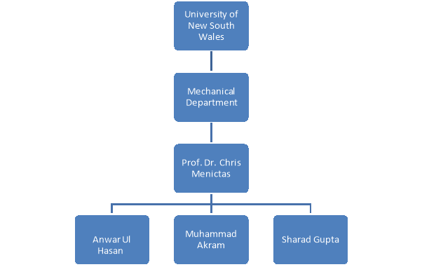
CE 3.1 It was during my second semester of Masters for Mechanical Engineering in UNSW, my father decided to lay the foundations of our new house back in Pakistan. I requested my father to refrain from hiring a contractor to install central air conditioner. The trigger being the fact that I had learnt fundamentals of Heating, Ventilation and Air Conditioning (HVAC) during my Bachelors of Mechanical Engineering and I wanted to gain some more knowledge in my Master’s degree, only to design my own HVAC system in my newly built house. I studied Refrigeration and Air Conditioning (RAC) in UNSW, Sydney in the same time and completed a project under Professor Dr. Chris Menictas.
Background
CE 3.2 The day is still vivid clear in my mind. I was in sixth grade when my father had to throw food in the bin as it went stale due to broken fridge. The technician came in to fix the black round box (later I learnt it was a compressor) – I welcomed him with lots of annoying questions. He was patient enough to quench my thirst of questions and before leaving he handed me out a mini booklet which was nothing less than a wonderland.
The book taught me about the essentials and importance of Refrigeration and how our life is predominantly dependent on it. The curiosity and drive to know more about it landed me in my Bachelors degree of Mechanical Engineering as the prospectus was full of the RAC (Refrigeration and Air Conditioning) course insights. Since then, I had never looked back and grew more confident to fit air conditioning system in my home.
UNSW is rated amongst the top ranked universities around the globe. State of the art laboratories and updated softwares always give you an added advantage over your peers. Blessed enough to widen my engineering horizons in UNSW, I came across an RAC software named as CAMEL which trimmed my engineering skills in a positive way. I would sit in the laboratory and play with it for hours to pick up my game and I did very well as in the same course I was honored to head a project and perform heating and cooling load calculations of a newly constructed building composed of two floors divided into two zones – upper zone , Z1 & lower zone Z2.
Nature of Project
CE 3.3 This project included the calculation of heating and cooling load of two story building. The calculations were done manually and through famous load calculation software known as CAMEL. Furthermore, it also included different suggestions and techniques on how load reduction can be achieved in the apartment through variations in apartments structures.
Objective of the Project
CE 3.4 The overall objective of the project was to get real life experience related to load calculations of practical situations. Latent and sensible load had to be calculated including all the real-world possibilities and safety factors. In this project, the calculations of heating and cooling loads of a newly built building are performed. The building comprises of two floors. Ground floor has three sections and first floor has two sections. VRV (Variable Refrigerant Volume) units as air-conditioning were chosen for each level. Other than this, a couple of suggestions were made on reduction of load and increasing the air-conditioning capacity.
Nature of My Particular Work Area
CE 3.5 In this project, I was acting as the team lead role. I was responsible for several tasks of which some are listed below:
- I performed initial readings for the project
- I coordinated between my professor and team members.
- I was responsible for project planning and progress tracking.
- I calculated the loads of ground floor through manual calculation.
- I compared the manual results to the results of CAMEL software.
- I compiled the report and made technical presentation
The way I implemented my project and people management strategies, led my team mates follow in the same footprints to lead their own projects. The chain reaction feed back of developing leaders came to me as a joy and I take pride in it.

CE 3.6 Organizational Structure
Personal Engineering Activity
CE 3.7 First, I divided the project into four major parts and summoned a meeting of my other team members to designate their duties. I made a report on Primavera to set deadlines for the project. One partner was allocated the load calculation of first floor, one was assigned to do software simulations on CAMEL and last one had to make suggestions on how to decrease the load through changes in structures of home. I emailed all of this to my professor too.
CE 3.8 To calculate the load manually, I had to use the manual “DA-09” to get all the values related to the correction factors, transmission coefficients, absorptivity, reflectivity. My supervisor helped me in understanding how to use the manual. CAMEL was a new software for all of us. So, there were two lab sessions designed to familiarize ourselves with software. Supervisor helped us with all the basics of the software. To get good experience of using it I decided to arrange meetings of all group members so that we could sit together and learn as much as we could through the tutorials and knowledge of individuals. These meetings also helped to understand the manual DA-09, which was very important. As for the most of the calculations we had to get data from the manual. At weekends, every group member had to present the work done during the week. It helped in keeping the track of the progress. These informal meetings helped to keep the harmony and understanding among the group members. If someone was lagging, he was encouraged and helped if required.
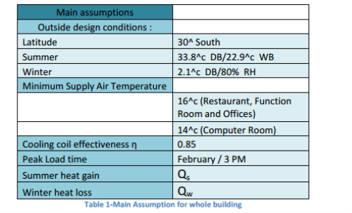
CE 3.9 I kicked off with the first tier which was research on internet and read books and discussed it with my professor. My major job was to calculate heating and cooling load of ground floor. I researched the major factors of heating a certain place. I made a complete list of them and started with calculations on each of these things. I also made a list of assumptions and the design parameters we already have from our professor.
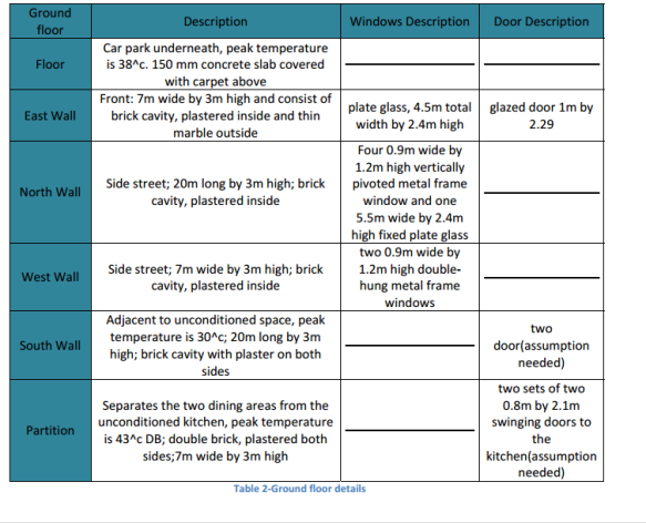
CE 3.10 The second most important task was to know the structure of ground floor. This was already provided to us by our professor. Below is the table which contains all the required data to calculate the loads of the ground floor.
CE 3.11 Calculations followed next. The first calculation was of heat gain through each component of the room i.e. floor, roof, walls, windows, electric appliances, doors, glass walls etc. The basic formula used to calculate heat gain through glass windows is given below.
Area * Q (w/m2) * correction = Heat gain
Solar heat gain is represented by Q. And every glass window has its own correction factor. These values were taken from the manual “DA-09”. This formula was used for every glass component which was facing sunlight directly. Sample calculations for the glass on west and north are given below:
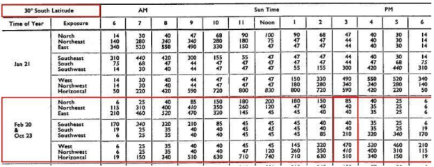
Table 1: Solar heat gain through reference glass (w/m^2)
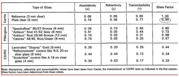
Table 2: Solar characteristics and glass factors
- West: 2 * 0.9 * 1.2 * 470* 0.94/0.85= 1122.7 W (2 windows .9 x 1.2 m each 0.85 cooling coil efficiency)
- North: 2* 0.9 * 1.2 * 85 * 0.94/0.85=203.04 W
The values of solar heat gain and correction factors were taken from the table 1 & 2 respectively.
CE 3.12 The next part was to calculate solar and transmission gain through walls and roof. Now the equation for heat transfer through the wall is:
Q = (Area) * (Equivalent Temperature Differences) * U
Here, U represents transmission co-efficient and the value for transmission co-efficient for the material was taken from the manual.
Sample calculations for the transmission gain through West, North and South walls are given below. Values for “U” and Equivalent temperature difference are taken from Table 3 & 4.

Table 3: Equivalent temperature difference (C0)
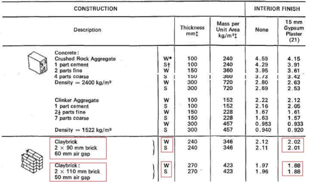
Table 4: Transmission coefficient U-masonry walls (W/m2C)
- West: 18.84 * 12.8 * 2.01 = 484.71 w
- North: 12.84 * 16.1 * 2.01 = 415.51 w
- South: 12.71 * 6.7 * 2.01 = 171.165 w
Total Solar and transmission through walls is 1071.385 w
CE 3.13 Transmission gain through partitions between different rooms on ground level, doors, glass walls, floor, ceilings were also calculated for correct estimation of the total load. Transmission coefficient for each surface was different due to their material and was taken directly from the manual. Area and temperature difference of each surface was calculated before calculating heat gain.
CE 3.14Temperature of the car park was more than the temperature on the ground level so heat was to be transmitted through the floor. To calculate this, I simply calculated the temperature difference, transmission coefficient of the floor and area. For ceiling, because the temperature is the same on the both sides, so, there was no heat transmission through ceiling.
CE 3.15 The next part is to calculate the internal heat due to people present in the room. Number of people, diversity factor and heat gain from people was used to calculate the sensible heat gain through people. I used the following equation for this.
Q = no of people * diversity factor * heat gain from people
It was assumed that the number of males and females were equal. Metabolic factor for the female is 0.85male. Diversity factor and heat gain from people were taken from the manual.
CE 3.16 The next step was to calculate the heat from the light sources on the ground floor. Different assumptions were made on the area of ground floor that how much light intensity would be needed. Then based on this light intensity the heat from the lightening sources were calculated. The equation used for this purpose was.
Q = Area (m2) * 20 (watt/m2) * diversity factor * storage load
CE 3.17Now the next step was to calculate heat generated from different appliances in the room. We had to assume all the devices that can be present in a generic apartment. These include coffee maker, dishwashers, refrigerators and stuff like this. Manual was to take the value of heat gain for different appliances. A range of different appliances was included in the manual. Based on these things the load calculation was done. Similarly, calculations were made about the food being cooked in the kitchen. Safety factor of 5% was used while calculating the total sensible heat from all the sources to tackle any mistake while calculating the load
CE 3.18 Internal load had two components; sensible, latent. After calculating total sensible heat, I calculated the total latent heat as well. Safety factor of 5% was used for the total latent heat. After the heat gain was calculated from different resources I had to add these values and calculate the end results. Below tables show the end results of these values. Zone 1 represents the ground floor.
CE 3.19 After calculating the total heat gain in summers, all the calculations were repeated using the conditions for the winters and heat loss was calculated for all individual components. Which was in the added up to get the total heat loss in winters. Qs represents the heat gain in summers and Qw represents the heat loss in the winters.
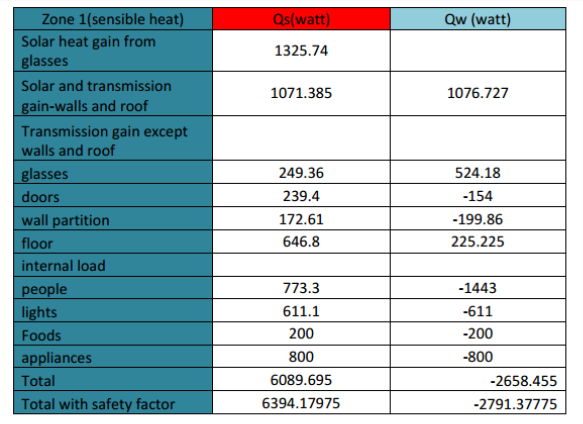
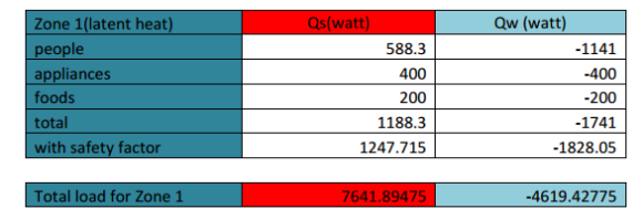
Table 5: Results for zone1 (sensible and latent heat)
CE 3.21 Now next step was to compare the results of these with simulation results. Me and my colleague compared the results. There was a little bit of difference in the results. This was since CAMEL is advanced software and it accounts for every little thing. Manual calculations are very long process and there is always a little chance of error in it.
CE 3.22 To suggest any structural changes in the building for the reduction of overall load, I added different features in the structure i.e. added shades on the windows, reduced the windows area, used different partition materials and wall thickness. I used the CAMEL simulation to see the effect of these changes. By changing some of these parameters I could reduce the load to some extent.
Summary:
CE 3.23 The day I completed this project I called my dad and asked him to send me blue prints of the house. I started comparing my experimental calculations with my house loads to procure optimum ventilation system components. After three weeks of hard work, I installed the system in my house. I think for me it was nothing less than pulling off a miracle. Starting off with the HVAC basics book, given by the technician to the HVAC course in my Bachelors, then earning a Master’s degree and finally ending up designing my own HVAC system based on those heating and cooling calculations reference was nothing less than a dream come true. I really do feel proud of my efforts. So, I would like to conclude by saying that this project helped me achieve my goals – to speak of which, as of now, I am on a video call with my dad back in Pakistan who is sitting in that comfy room.
Cite This Work
To export a reference to this article please select a referencing stye below:
Related Services
View all


DMCA / Removal Request
If you are the original writer of this essay and no longer wish to have your work published on UKEssays.com then please click the following link to email our support team:
Request essay removal