Smart Transport System Based Upon Autonomous Road Vehicles
| ✅ Paper Type: Free Essay | ✅ Subject: Engineering |
| ✅ Wordcount: 4264 words | ✅ Published: 31 Aug 2017 |
People have a high reliance on car for their daily travel to work, shopping, tour and many other places [1]. More than 50% of world’s population lives in cities and more vehicles are on the road causing congestion problems and accidents. Therefore, there is a need for more safe and efficient means of transportation. The new technologies are replacing decade old transportation frameworks and operators with computerization and automation. Intelligent Transportation System (ITS) is an innovative method that utilizes sensors movements, artificial intelligence, and human management together which will help the autonomous vehicle to drive without human intervention [2]. Autonomous vehicles will be seen soon on our roads communicating with nearby vehicles and warn each other by understanding the conditions ahead. Many cars, for example, the Tesla Model S and the Volvo XC90 has already started including propelled self-driving capacities, and this is expected to increase in coming years [3].
In this paper two use case scenarios of autonomous vehicles are discussed. The first use case discusses about an autonomous vehicle valet parking. Parking a vehicle is considered as one of the difficult task in driving. This includes finding the parking slot and park without collision. The proposed system will allow the driver to leave the vehicle when he/she reaches the destination and the vehicle will park itself in a parking slot.
The second use case discusses an autonomous vehicle that can drive without human intervention in an unknown environment. The use cases included are obstacle avoidance, backward moving and overtaking.
2.USE CASE SCENARIOS
2.1 AUTONOMOUS VEHICLE VALET PARKING
The number of vehicles on road is increasing rapidly causing congestion problems and pollutions. One of the main reasons for this is lack of car parking and time consumed to find the parking slots. This paper discusses the driving and parking of an autonomous vehicle to a car parking slot without human intervention. An autonomous valet parking will allow the driver to leave the vehicle when he/she reaches the destination and will park the vehicle in a parking slot. The sensors will sense obstacles in its way and will steer around them to avoid collision. It will also notify the driver after parking and locking the door automatically through an app. The proposed system will help the driver who is in a hurry to attend a meeting or watch movie, who doesn’t want his/her time to waste checking for parking area and to drive and park there.
There are three systems in the vehicle for the autonomous vehicle valet parking [6].
(i) Server System
The server system will generate the different driving path to the nearest parking slot and will provide it to the driver through the mobile application. The driver can select the preferred path and vehicle will drive through that path.
(ii) Mobile System
The driver will be able to monitor the vehicle and check whether it is finding any difficulty to reach the parking slot. The vehicle will also notify the driver once when it has reached the parking slot.
(iii) Vehicle Control System
The control system will generate the control signals such as steering control, gear change, brakes and speed control required for the movement of the vehicle through the provided path. It should also generate control signals to help the car park in the provided slot.
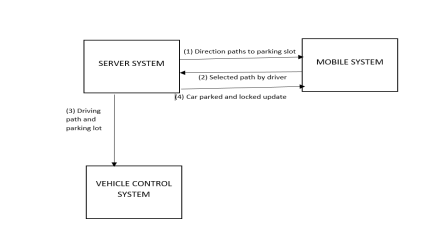
Figure 1: Autonomous vehicle parking system
2.1.1 DESIGN ANALYSIS AND ALGORITHM
2.1.1.a. PARKING SLOT SELECTION
Once the driver has reached the destination the driver should request for the nearest parking and reserve the parking slot. The algorithm for this is shown in figure 1.1 [6].
Step 1: Driver request for the parking guidance.
The parking slot availability in the parking garage should be updated every time in the data base. The parking slot can detect whether it is occupied with vehicle or not by using an IR sensor in the parking slot. The IR sensors will be connected to micro-controllers. The microcontrollers will communicate to the central server system using ESP8266 which contains the data base of the parking slot availability. ESP8266 is a low-cost Wi-Fi chip which will give micro-controller access to communicate with the Wi-Fi network. Along with the number of free parking lots, parking cost in different parking garage will also be stored in the database. The parking guidance is requested by the driver using the navigation system which will be embedded with sim cards inside the vehicle. BMW already have sim card embedded cars [8]. There will be GPS module inside the navigation system which will give the current location of the car. This location of the vehicle, will help to find the nearest parking facilities near it. The distance and time to reach each parking garage are calculated by the already programmed navigation device. It will also provide the parking fare for each parking garage. The driver can then select the appropriate parking slot based on his convenience.
Step 2: Reserve the parking slot
Once the parking slot has been selected by the driver, it should be reserved otherwise there are chances for the parking slot to be occupied by some other car before the vehicle reaches the selected slot. The central server system should be updated once the driver has reserved parking slot. The reservation should be done using the number plate of the vehicle. Sometimes, there might be more than one reservation request for the same parking slot at the same. So, there are chances to get the reservation declined for other customers. In that case the driver can select another parking slot. The vehicle can also go to the parking slot without reservation as well. But there will be a risk of the parking slot to be occupied before the vehicle arrives the parking slot.
Step 3: Start the navigation to the parking slot.
Once the parking slot has been selected by the driver, he/she can leave the car and the car will navigate to the selected parking slot.
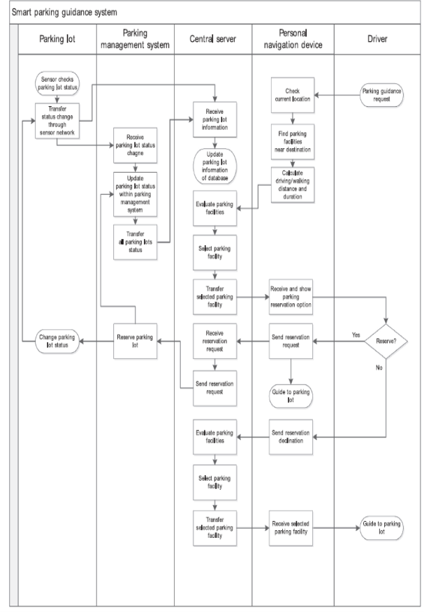
Figure 1.1. Algorithm for parking slot selection
2.1.1.b. PARKING PATH FOLLOWING
Once the parking slot has been selected the next step is to guide the vehicle to the parking slot. In this paper [6], a graph data structure is used, which will generate driving path using 4D kinematics (i, j, θ, R). The i and j represents the centre co-ordinates of the vehicle and θ is the heading angle value of the vehicle. To avoid the obstacles while following the path to the parking slot laser scanner sensors (LMS15) are used. These sensors can see the obstacles within 40 m distance and an angular range of 0-1900. The sensors are fitted on both sides in the front and rear side of the vehicle. The obstacle avoidance path is generated by the server system. The figure 1.3. [6] shows the obstacle detecting and avoiding path.
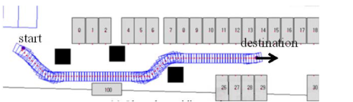
Figure 1.3. Obstacle detecting and avoiding path [6]
The path generated by the server system consists of location of the vehicle and it’s heading angle value (θ). The vehicle control system will generate signals to control the steering of the vehicle depending on the heading angle value and location of the vehicle. The steering angle should be calculated for this. The formula for steering angle is shown below [6].
θs = θ3 – θ2 - θ1 2
θs = Steering angleθ3 = lateral error angle of vehicle location θ2 = look-ahead way point heading angle θ1 = vehicle heading angle
Figure 1.4. [6] shows the driving path followed by the vehicle and the location of the vehicle.
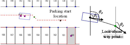
Figure 1.4. Driving path followed by the vehicle [6]
The speed will also be controlled by the control system. The speed will be reduced to 8 km/hr once the car has entered the parking garage. The car will be notified when it reaches the parking garage by the GPS module installed in the navigation system. The laser scanner sensors can detect the moving obstacles as well. When the vehicle has detected the moving object (e.g. pedestrian) it will stop and wait until it has crossed the road.
2.1.1.c. PARKING AT THE SELECTED PARKING SLOT
The next step after reaching the parking slot is the parking at the selected slot. The vehicle control systems consist of two levels [7].
1. Low level control – Low level control is the control of motion which includes steering wheels’ control, speed control and moving in a proposed distance.
2. High level control – High level control is computer vision based control. A trajectory path is formed showing the vehicle direction to park it in the selected slot.
To describe the car parking, bi-cycle model is used [7]. This model is commonly used to describe four wheeled vehicles. Rear drive wheel of this model cannot be rotated. To control the vehicle movement the front wheel will be rotated about the vertical axis following the trajectory path. It is assumed that the vehicle is moving on a horizontal and flat surface.
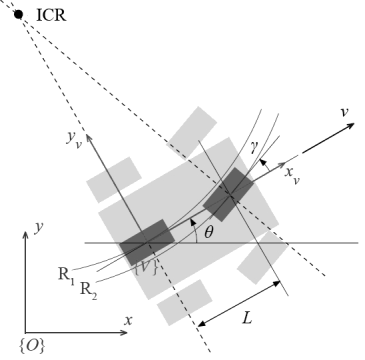
Figure 1.5. Bi-cycle model of four wheeled vehicles
The figure 1.5. shows the bi-cycle model of four wheeled vehicles [7]. The co – ordinate system is represented as ‘V’, where x and y represent the co-ordinate points in that system.
L= distance between the front and rear wheels
γ = steering angle
θ = angle between xv and x
v = velocity of the vehicle
ICR – instantaneous centre of rotation of the vehicle
Parking of the car can be done in two ways. [7]
1.Parallel parking method.
2.Perpendicular parking method.
Parallel parking method
A precise path should be generated to minimize the parking area. The vehicle should move along two arcs created by the high – level control without straight-line section between them. A maximum rotational angle of the steering wheels is required to achieve this. The figure 1.6. shows the parallel parking method [7].

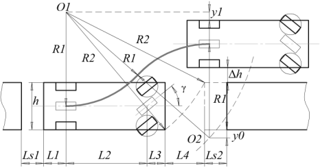
Figure 1.6. Parallel parking method [7]
The circle radius is calculated using the steering angle (γ).
Circle radius (R1) = L2tgγ
Ls1 and Ls2 are the safety boundaries, so the vehicle will not hit the front and back corner of the vehicle while parking. L1, L2, L3 and L4 are the boundary dimensions.
The trajectory parking length (S)can be calculated to park the vehicle in the parking slot without colliding on the obstacles. The formula to obtain the trajectory parking length is given below.
S = Ls1 + L1 + L2 + L3 + L4 + Ls2
Perpendicular parking method
Perpendicular parking method is almost like the parallel parking method. This method reduces the parking area required for parking. The figure 1.7. shows the perpendicular parking method.
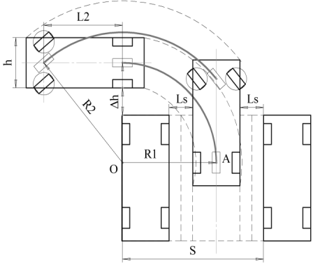
Figure 1.7. Perpendicular parking method [7]
The centre axel wheel should steer along the arc with the radius (R2) value given below to park in a safe condition.
R2 = 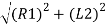
When vehicle reaches point A,for successful completion of parking, the steering wheels should be controlled by the steering. The gear should be in reverse gear and continue until the safe region. There are safety zones LS as in the parallel parking method. The trajectory parking length (S)can be calculated to park the vehicle in the parking slot without colliding on the obstacles. The formula to obtain the trajectory parking length is given below.
S = R1 + L2 + LS + 
2.1.1.d. NOTIFYING THE DRIVER AFTER PARKING
After the car, has been parked in the parking slot, the driver should be notified that the car is safely parked. The sim card embedded in the system will help to notify the driver through SMS or mobile app that it has arrived the parking slot safely. This will help the driver to track the vehicle and ensure that it has reached the parking slot safely.
2.1.2 CHALLENGES AND DESIGN ISSUES IN THE PROPOSED SYSTEM
Challenges
(i) One of the main challenges in the proposed system is that the driver can only access the parking garages which has been saved in the central server system.
(ii) In the proposed system, the vehicle will not come to pick the driver. He/she should go to the parking slot to find the car. This can be included in the future development.
Design Issues
(i) Sometimes GPS might fail to work in that case the autonomous car might fail to find its direction.
(ii) Infrared sensors are expensive and sometimes fail to work due to temperature change.
2.1.3. VEHICLES THAT HAS BEEN USING AUTOMATED VEHICLE VALET PARKING
Using digital mapping technology, BMW i3 is about to launch their new car [9] that can park in multi-storey parking garages. This fully autonomous vehicle will drive until it detects a free parking space. Their new ‘Remote Valet Parking Assistant’ will parks the i3 without any driver assistance. The new car can also detect the moving obstacles and falsely parked car using its LiDAR sensors and drive accordingly without colliding with the obstacles. The car will not notify the driver it has reached the parking slot is one of the drawback in their features.
2.2 AUTONOMOUS VEHICLE NAVIGATION IN UNKNOWN ENVIRONMENT.
A fully automatic vehicle should be able to drive by itself and for that it should sense, control, observe and react to its environment. This paper describes an autonomous vehicle that can drive without human intervention in an unknown environment. The use cases included are obstacle avoidance, backward moving and overtaking. The car will reach its destination by avoiding obstacles and following the path lane. A fuzzy logic control technology is used in this paper which will receive the required information from the sensors which will sense the obstacles in its way and the environmental changes. A GPS module is also used to track the position of the vehicle. The system will also control the speed, brake and steering effectively.
2.2.1 DESIGN ANALYSIS AND ALGORITHM
The proposed system is divided into two units [5]
- Fuzzy logic control unit
- Computer vision unit.
The block diagram of the proposed unit is shown in the figure 2.1. [5].
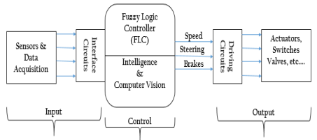
Figure 2.1. Block diagram of the proposed system [5]
2.2.1.a. FUZZY LOGIC CONTROL UNIT
Autonomous cars are very complex to design. In this system, fuzzy logic is used to generate logical control signals from the input analog signals. Fuzzy logic is widely used in artificial intelligence. There are many alternative approaches such as genetic algorithm and neural network, but fuzzy logic has the merit that, it can be easily understood by the human operators.
The block diagram of the fuzzy logic control unit is shown in figure 2.2.
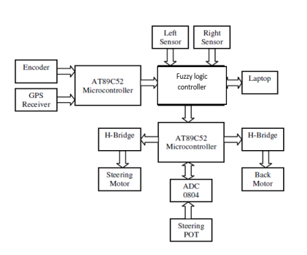
Figure 2.2. Fuzzy Logic Control Unit [4]
The proposed system consists of two ultrasonic sensors for recognising the obstacles and measuring the distance between the obstacle and vehicle. Ultrasonic sensors produce ultrasonic waves, which will not produce any sound pollution/environmental pollution. It’s also inexpensive. A H-Bridge is used to control the steering motor and the back motor. Webcam is used to see and follow the road lane path. The steering angle is measured and controlled by a potentiometer. The GPS receiver senses the position of the vehicle and is given to the microcontroller. This will help the micro-controller to know whether the vehicle has reached its destination or not. The steering and speed commands are combined and based on this the vehicle will move through the lane.
The speed of the vehicle is the most important part while driving. The speed of the vehicle depends on many external factors such as environmental condition, road condition and car condition.
For a normal autonomous car, it should have an auto-braking system, auto-speed control system and auto-steering system. These systems depend on different factors like environmental condition, car condition, road condition and so on. The fuzzy logic control unit will control the speed, brake, and steering based on these factors.
The figure 2.3. [4] below shows the fuzzy logic controller controlling the systems based on the environmental condition and car condition.
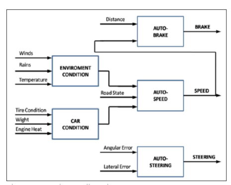
Figure 2.3. Fuzzy Logic Controller [4]
Auto-braking System
The auto-braking system is provided in autonomous car to avoid collision. The ultrasonic sensors will sense the distance between the obstacle and the car and if it is not in a safe distance the car will either stop or reduce the speed.
The normal speed limit is set as 0 – 60 km/hr and the minimum distance between the car and the obstacle is maintained at 5 – 10 m. This is selected as per the traffic safety authorities.
Auto- speed System
Speed of the car is controlled on various factors such as environmental condition and car condition. Environmental condition and car condition will be between the range shown below and the car should choose the speed accordingly.
Environmental Conditions:
– Rains falling: (0 – 200) mm.
– Winds Speed: (0 – 150) km/h.
Rain sensors are used to sense the rain. The sensors can tell when it is raining depending on the rain drops falling on the wind shield depending on the light reflected. If there are more rain drops on the wind shield less light will be reflected to the rain sensor.
Car Condition:
– Weight (including passengers): (1600 – 1900) kg.
– Engine Heat: (-25 – 65) Í; c.
A weight sensor can be used in the seats so that it will sense how many passengers are there in the seat and the vehicle can control the speed.
All these factors are given a rating between 0 and 10 [4]. If the conditions are bad, the rating will be between 0-3 and if the conditions are good, then the rating will be between 7-10. The micro-controller will be pre-programmed in such a way that it will be indicated when it’s raining, or when the air content in the tire is less and the speed of the car will be controlled according to that.
Auto-Steering control
The steering control is the main part of the autonomous car. The steering is controlled in such a way that; it will follow the trajectory or path to the destination generated by the computer vision unit.
Obstacle Avoidance
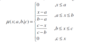
The main feature that should be incorporated in an autonomous vehicle is obstacle avoidance to avoid collision. There are two type of obstacles static and moving obstacles. The obstacles are sensed by the ultrasonic sensors which are connected at the right and left side of the vehicle at an angle of +45o and -45o. The distance is measured using fuzzification. The fuzzy sets used are adjacent, medium and far. The range is set between 25 m and 85 m and is determined by the sensor and the dimension of vehicle [4]. Any measured value by the sensor that is below 25 m is set as minimum value and any measured value exceeding 85 m is set as maximum value. To determine in which fuzzy set (near, medium or far) the measured sensor value belong to is determined using triangular membership function. The equation for that is given below [4].
The speed control and steering control signals are got as an output from the controller which are then given to the steering motor and back motor. The steering is controlled by the steering motor. The steering will be turned according to the steering control signals. The steering angle is controlled by the potentiometer. The digitized value of steering angle decision is shown below.
Large Left – 120
Small Left – 145
Straight – 170
Small Right – 195
Large Right – 220
Figure 2.4. [4] shows the graphical representation of the steering angle decision.
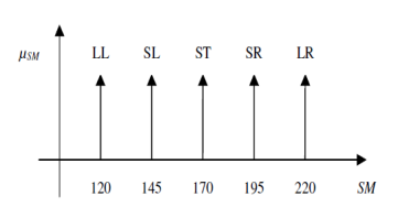
Figure 2.4. Graphical representation of the steering angle decision [4]
Similarly, the speed is controlled by the back motor and three commands are used for this – Slow, Medium and Fast. The values for this is shown below and is decided by the back motor’s duty cycle values for pulse width modulated signal.
Slow – 20
Medium – 50
Fast – 80
Figure 2.5. [4] shows the graphical representation of speed control decision
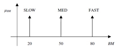
Figure 2.5. Graphical representation of speed control decision[4]
Destination Arrived
A GPS receiver is attached to the controller to know whether the autonomous car has arrived its destination. The destination will be already decided and entered by the user to the micro – controller by using a mobile app. The car and the user can communicate to each other using the 4G network. A SIM card will be already embedded inside the car. Once the car has arrived the destination the car will notify the user.
2.2.1.b COMPUTER VISION UNIT
Computer vision unit does the decision-making process in the system. In this paper, overtaking and backward process are discussed. Computer vision unit extracts information from the images taken from multiple cameras and makes decision when to overtake other vehicles and when to reverse the car.
Backward direction
The figure 2.6. [5] shows the algorithm for backward process of the vehicle.
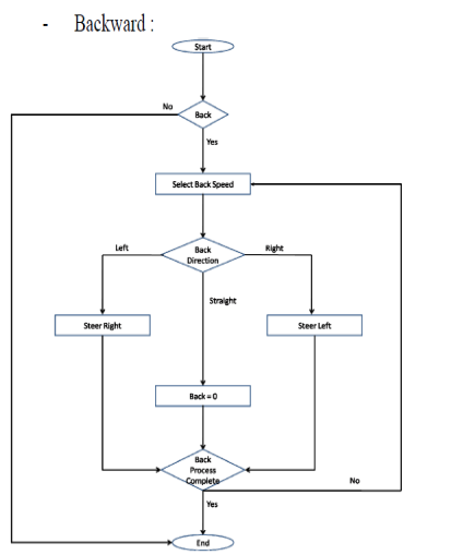
Figure 2.6. Algorithm for backward process [5]
Step 1: Decide whether the car should take backward direction or not.
Step 2: If yes, the car should select the speed of the vehicle to move in backward direction. If not, then the car continues to move in forward direction.
Step 3: After selecting the speed of the backward movement, the next step is to select the direction of the backward movement. If the car wants to move left, then steering should be turned to right and if the car wants to move right then the steering should be turned left. If the wants to move backward in a straight direction then the steering should be kept straight i.e., no change for the steering.
Step 4: After the step 3 the car will check the backward process has been completed and the process comes to an end.
Overtaking
Overtaking is a difficult process normally done by human drivers. To overtake another car the vehicle should maintain a certain speed limit and distance between the two cars should be in a safe distance so that it will not collide. The algorithm for a safe overtaking is given in the figure 2.7. [5].
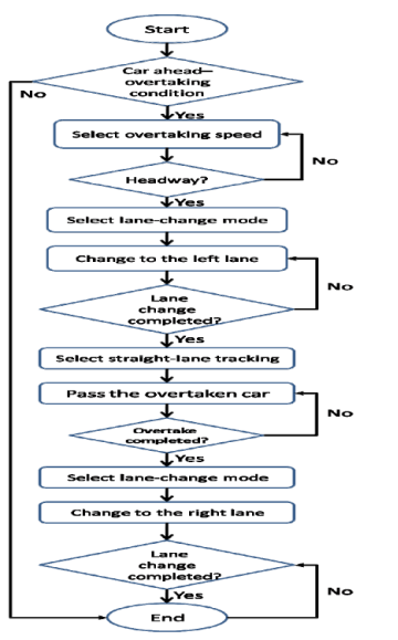
Figure 2.7. Algorithm for overtaking [5]
Step 1: The autonomous car will decide whether to overtake the other car in front of it which will be moving slower than it. If yes, then it should select the overtaking speed. If not, then the car should continue the previous speed.
Step 2: The autonomous car should change to the left lane after deciding the speed to overtake. It should check through the rear camera that no other vehicles are trying to overtake it in the left lane, otherwise the two cars will collide with each other.
Step 3: After changing to the left lane the autonomous car should continue to move in straight direction. It should check whether it has overtaken the slow vehicle. If yes, then it should change to the right lane maintaining a safe distance. If not, it should continue to move in straight direction and keep on monitoring whether it has overtaken the slow vehicle.
Step 4: After the change of lane the autonomous car should check whether it has completed the lane changing. If yes, then the process comes to an end.
2.2.2 CHALLENGES AND DESIGN ISSUES IN THE PROPOSED SYSTEM
Challenges
(i) In the proposed system, only the algorithm for overtaking and backward movement has discussed. Artificial intelligence algorithm has not been discussed.
(ii) In the proposed system, there is detection of traffic signals which can be incorporated in the future development
Design Issues
(i) Sometimes GPS might fail to work in that case the autonomous car might fail to find its direction.
(ii) Ultrasonic sensors can produce some errors when sensing objects which might result in collision.
2.2.3 AUTONOMOUS CARS ALREADY IN MARKET
Fully autonomous car will be on our road by 2021. Many car companies like tesla, google, BMW has already started developing such cars. Google’s self-driving car has completed 1,500,000 miles in full automated mode on mar 2016 [10]. This car has no steering and brake pedal. It has laser and radar sensors to sense the obstacles and also have a back-up steering, braking, and computing system if any of these fails.
3. CONCLUSION
To conclude, we will be able to see self-driving cars on our roads soon, addressing all the road problems like congestions, parking problem, accidents and so on. In this paper two use cases have been discussed. In the first use case, a server system, mobile system and vehicle control system are used for autonomous vehicle valet parking. The proposed system will drop the diver/user at his/her destination and will park the vehicle in the parking slot selected by the user. The future development of the system can be made by making the car to go and pick the user from the parking slot, when he/she is ready to leave. The second use case describes an autonomous vehicle that can drive without human intervention in an unknown environment using fuzzy logic. The use cases included were obstacle avoidance, backward moving and overtaking. The block diagram and algorithm of the proposed system are described in the paper.
REFFERENCES
[1] C. F. Lin, J. C. Juang and K. R. Li, “Active collision avoidance system for steering control of autonomous vehicles,” in IET Intelligent Transport Systems, vol. 8, no. 6, pp. 550-557, Sept. 2014.
[2] Mohammad Abdul Qayum, Nafiul Alam Siddique, Mohammad Abtiqul Haque and A. S. M. Tayeen, “Control of autonomous cars for intelligent transportation system,” 2012 International Conference on Informatics, Electronics & Vision (ICIEV), Dhaka, 2012, pp. 377-382.
[3] B. Brown, “The Social Life of Autonomous Cars,” in Computer, vol. 50, no. 2, pp. 92-96, Feb. 2017.
[4] U. Farooq, K. M. Hasan, M. Amar and M. U. Asad, “Design and implementation of fuzzy logic based autonomous car for navigation in unknown environments,” 2013 International Conference on Informatics, Electronics and Vision (ICIEV), Dhaka, 2013, pp. 1-7.
[5] A. H. A. Widaa and W. A. Talha, “Design of Fuzzy-based autonomous car control system,” 2017 International Conference on Communication, Control, Computing and Electronics Engineering (ICCCCEE), Khartoum, Sudan, 2017, pp. 1-7.
[6] K. W. Min and J. D. Choi, “Design and implementation of an intelligent vehicle system for autonomous valet parking service,” 2015 10th Asian Control Conference (ASCC), Kota Kinabalu, 2015, pp. 1-6.
[7] D. M. Filatov, E. V. Serykh, M. M. Kopichev and A. V. Weinmeister, “Autonomous parking control system of four-wheeled vehicle,” 2016 IEEE V Forum Strategic Partnership of Universities and Enterprises of Hi-Tech Branches (Science. Education. Innovations), St. Petersburg, 2016, pp. 102-107.
[8] The Economist (2014). The connected car smartphones on wheels
Available: http://www.economist.com/news/technology-quarterly/21615060-way-cars-are-made-bought-and-driven-changing-mobile-communications [Accessed 27/02/2017]
[9] Autocar (2014). BMW reveals new self-parking autonomous technology.
Available:http://www.autocar.co.uk/car-news/industry/bmw-reveals-new-self-parking-autonomous-technology. [Accessed 01/03/2017]
[10] Wikipedia, the free encyclopedia (2017). Autonomous car
Available:https://en.wikipedia.org/wiki/Autonomous_car [Accessed 04/03/2017]
Cite This Work
To export a reference to this article please select a referencing stye below:
Related Services
View all


DMCA / Removal Request
If you are the original writer of this essay and no longer wish to have your work published on UKEssays.com then please click the following link to email our support team:
Request essay removal