Comparison of High Voltage AC and DC
| ✅ Paper Type: Free Essay | ✅ Subject: Mechanics |
| ✅ Wordcount: 1669 words | ✅ Published: 23 Sep 2019 |
High Voltage AC
High Voltage AC Tests
Most of the test transformers are designed for operation at the working frequency of the test object. In a High Voltage AC system the equipment to be tested is continuously subjected to full power frequency voltage, allowing for some over voltage.
When performing AC tests the applied voltage is increased until flashover occurs. Voltage less than that which the flashover occurs is called flashover voltage.
Generating High Voltage AC
The test transformers in high voltage labs are used to step up the voltage from a lower AC voltage level to a desired one. A regulating transformer is supplied on the lower voltage side of the test transformer making it able to adjust the magnitude of the output voltage. Assuming that the turn ratio between the primary and the secondary is constant the output voltage can be calculated.
See figure ()

Figure 1
HV AC Characteristics
|
Ground Plane |
The High Voltage generated and measured in respect to a low impedance sheet connected to an earth electrode. |
|
Voltage Divider |
The Voltage is measured either with a resistive or a capacitive voltage divider. |
Two or more Cascade transformers are to be used when trying to generate more than 400 KV. The transformers are usually identical and the number of cascade transformers to be used depends on the desired voltage level.
Cascade Transformer Characteristics:
|
Windings |
Voltage level |
|
Primary |
Low |
|
Secondary |
High |
|
Tertiary |
Low |
The Voltage at the Tertiary winding is fixed to voltage V. The turn ratio between the primary and the tertiary windings in equal to 1.
The secondary winding of the first stage transformer is connected in series with that of the second stage creating a 2V potential difference between the terminal of the second stage transformer and ground.
All stages except have three winding transformers the top most stage which has two.
Stage 1 is earthed whilst the potential difference at stages above increments with value of V.
Stage 2 is V and stage 3, 2V and so on.
See figure ()

Figure 2 Cascade Transformer Circuit
High Voltage DC
Testing
HV DC tests are mainly used to apply pressure tests on HV cables and wires. Even though the cables might run on AC, AC testing is not used in that case. This is because of the high capacitance of the cables which necessitates AC tests with a high kVA rating to supply the capacitive current.
Applications
Application of HVDC include Testing in laboratories and facilities, manufacturing of semiconductors, Ionisers, TVs, X-Ray sources and more.
Advantages of HVDC TO HVAC
- Even though is cheaper to transmit HVAC over small distances, HVDC has lower losses compared for HVAC for long distance point-to-point power transfers making it cheaper for long distance use.
- HVDC allows the connection of asynchronous grids.
Methods of DC Generation
Van de Graff Generators
These type of generators are useful for very high voltage and low current applications. Van de Graaff generators can be either charged via a high-voltage power supply or via a belt and rollers. The generators are usually enclosed in an earthed cylindrical vessel and are operated under pressure or in vacuum.

An insulating belt is driven at speeds of 1000 to 2000 metres per generator minute by an electric motor. Charged particles are being send out on the belt from corona points at a voltage ranging between 10 to 100 kV compared to earth and is then removed and collected to an insulated metal electrode through which the belt moves.
https://science.howstuffworks.com/transport/engines-equipment/vdg3.htm

- Output Terminal: Aluminium or steel sphere.
- Upper brush: Fine Metal Wire.
- Upper roller Piece of Nylon.
- Belt Made from Insulating material.
- Motor
- Lower brush
- Lower roller Piece of nylon covered with silicon tape.
Rectifier Circuits
Valve rectifiers can be used for the generation of HV DC voltages up to 100 kV and with an output current of about 100 mA.
The table () shows the different rectifier circuits for producing HV DC from HV AC sources.
|
Type |
Description |
Circuit Diagram |
Output Waveform |
|
Half Wave Rectifier |
The capacitor is charged to the maximum AC voltage across the secondary of the HV transformer in the conducting half cycle of the diode. A Heavy and large value of capacitor needs to be used which will cause ripple problems. |
|
|
|
Full Wave Rectifier |
Diode A conducts and charges the Capacitor during the positive half cycle, while Diode B conducts and charges the Capacitor during the negative half cycle. |
|
|
|
Bridge Rectifier |
During the positive half cycle of the input voltage diodes and are in forward biased so current flows through AB and enters the RL Load. During the negative half cycle diode and become forward biased and so current flows through CB to the load RL. |
|
|
|
Cockcroft-Walton Multiplier Circuit |
The first stage of the Cockcroft-Walton Multiplier operates as a voltage doubler. At higher levels the circuit is repeated with cascade series of connections resulting in the formula for n number of stages. |
|
|


Recent Development
Use of a sphere gap as a calibration device for alternating and impulse peak voltage magnitude has been removed, however a sphere gap used in accordance with the standard is still considered an “approved measuring device”. The sphere gap is no longer considered valid for use when measuring direct voltages, with rod-rod gaps being specified.
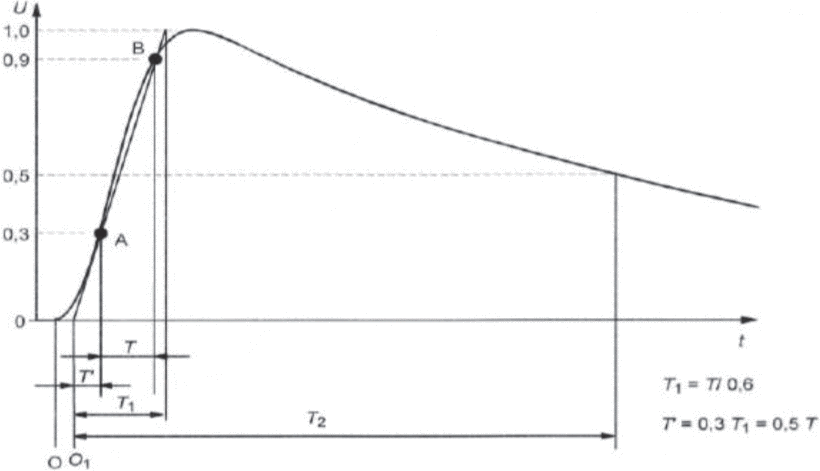
Impulses
Description
High Voltage Impulse generators can be used to produce output waveforms that contain parameters that are strictly given by IEEE standard and used to test HV equipment. The output waveforms can be of many shape including switching impulse, lightening or system fault.
The full lightning impulse
is composed by two exponential functions.

IEEE Standards for lightning impulse
Front-time
Impulse Peak Value = 30%
Impulse Peak Value = 90%
Half-time
This value defines the time interval from the virtual beginning to the time were the peak value drops down to 50%.
Testing
LTspice software can be used for the simulation of a HV Impulse generator. This simulation tool contains all necessary modules for these type of simulations as well as the advantage of using any number of nodes.

The evaluation of HV impulse waveforms is also done using model based Deconvolution. The Deconvolution algorithm uses the measured output y(t) and impulse response h(t) to calculate the input waveform x(t).
Impulse voltage tests are carried out on high voltage transformers cables, and insulators in order to access their resistance to high voltage transients.
To test the resistance of different types of wire a set of impulses of increasing voltage should be applied to the wire and partial discharge measurements of the wire should be taken each time an impulse is sent until wire failure.
Standards for Approved measuring systems
|
Measured Quantity |
Approved measuring system |
Reference measuring system |
|
Alternating voltage |
An approved measuring system shall be capable of measuring the peak or root mean square (rms) value of an alternating voltage with an overall uncertainty of not more than ± 3% in its range of use |
A reference measuring system shall be capable of measuring the peak or rms value of an alternating voltage with an overall uncertainty of not more than ± 1% in its range of use. |
|
Direct voltage |
An approved measuring system shall be capable of direct voltage measurement with an overall uncertainty of not more than ± 3% in its range of use. |
A reference measuring system shall be capable of direct voltage measurement with an overall uncertainty of not more than ± 1% in its range of use. |
|
Lightning and switching impulse voltage |
An approved measuring system shall be capable of full and tail-chopped impulse voltage measurement with an overall uncertainty of not more than ± 3% for peak voltage, and not more than ± 10% for time parameters, in its range of use. |
A reference measuring system shall be capable of full impulse voltage measurement with an overall uncertainty of not more than ± 1% of peak voltage for full and tail-chopped impulses, not more than ± 3% of peak voltage for front-chopped impulses, and not more than ± 5% for time parameters, in its range of use. |
High Voltage and High Power Testing Safety Practices
|
Number # |
Guide Description |
|
1 |
All ungrounded terminals of the test equipment or apparatus under test should be considered as energized. |
|
2 |
Common ground connections should be solidly connected to both the test set and the test specimen. As a minimum, the current capacity of the ground leads should exceed that necessary to carry the maximum possible ground current. The effect of ground potential rise due to the resistance and reactance of the earth connection should be considered. |
|
3 |
Precautions should be taken to prevent accidental contact of live terminals by personnel, either by shielding the live terminals or by providing barriers around the area. |
|
4 |
The circuit should include instrumentation for indicating the test voltages. |
|
5 |
Appropriate switching and, where appropriate, an observer should be provided for the immediate de-energization of test circuits for safety purposes. In the case of dc tests, provisions for discharging and grounding charged terminals and supporting insulation should also be included. |
|
6 |
High-voltage and high-power tests should be performed and supervised by qualified personnel. |
|
7 |
Consideration should be given to safety regulations which may apply to specific circumstances; for example, other IEEE guides, union, company, or government regulations. |
|
8 |
In the use of signal-gathering equipment, each device should be used in such a manner that it will not present a personnel hazard should it inadvertently become a part of the high-voltage circuit, or fail to function properly. |
- https://srirajkumar.files.wordpress.com/2011/06/cascaded-transformers.pdf
- http://www.dbc.wroc.pl/Content/3458/high_voltage_engineering.pdf
- https://studentcentral.brighton.ac.uk/bbcswebdav/pid-3281091-dt-content-rid-6179013_1/courses/EO632_2018/9%20HVDC%20Generation.pdf
- https://www.slideshare.net/RP6997/generation-of-high-dc-voltage-hvdc-generation
- http://www.circuitstoday.com/full-wave-bridge-rectifier
- https://ieeexplore.ieee.org/mediastore_new/IEEE/content/media/7510547/7520888/7521736/7521736-fig-1-source-large.gif
- https://ieeexplore.ieee.org/document/694840
- https://ieeexplore.ieee.org/abstract/document/4233816
- https://ieeexplore.ieee.org/document/6515981
- https://ieeexplore.ieee.org/document/6515981
- http://sci-hub.tw/http://ieeexplore.ieee.org/xpl/artic%C2%ADleDetails.jsp?arnumber=578032
Cite This Work
To export a reference to this article please select a referencing stye below:
Related Services
View all


DMCA / Removal Request
If you are the original writer of this essay and no longer wish to have your work published on UKEssays.com then please click the following link to email our support team:
Request essay removal